UML diagrams for the E-learning System. Following are the different UML diagrams like Components, Activity, Use Case, and Sequence diagrams of the E-learning System.
With the help of these diagrams, one can get a better understanding of the project.
UML Diagram for E-learning System
In this article, we have put together the structural UML diagrams i.e. component diagrams, and three types of behavioural UML diagrams i.e. Activity, Sequence, and Use Case diagrams for the E-learning System. We have also covered this project’s data flow diagram (DFD).
This is developed to manage e-learning activities on a single platform where students, faculty, and facilitators(Admin) can have a single medium through which they can manage all the activities safely.
Component diagram for E-learning System
Component diagrams are essentially class diagrams that focus on a system’s components that are often used to model the static implementation view of a system. The components are connected by lines representing relationships within the systems.
In the diagram, it can be seen that there are components namely students, courses, adding new courses, faculty, and subject. There are three users that can access the system. One is the Facilitator, the faculty and the Student.
The facilitator can manage any details related to the students, faculty, courses, and subject in the system. A facilitator will be allowed to add/remove any student and faculty member. The facilitator will be responsible for adding study material and new topics into the system.
Students can search for courses and enrol for the same. Students can also post queries. Students can enrol for courses and track their performance, and can also view their learning path.
Faculty can answer and resolve students’ course-related queries.

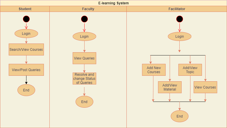
Activity diagram for E-learning System
Activity diagrams in UML display the functionalities of various activities and flow in management processes and software systems. The flow in the activity diagram can be sequential, branched, or concurrent.
The facilitator will be responsible for maintaining the system and also, keeping a check on faculty members, courses, information about courses, subjects, etc.
The facilitator can View and Add/EDIT/Delete new faculty, student and students into the system. The facilitator can View and Add/EDIT/Delete new subjects and courses into the system. The facilitator can manage subjects, students and faculty members. The facilitator can add course-related study materials for students.
Whereas, Student members can manage and maintain their profile. Students can access study materials, can post queries, and course details.
Sequence diagram for E-learning System
Sequence diagrams in UML are used to illustrate the sequence of messages between objects in an interaction. A sequence diagram consists of a group of objects that are represented by lifelines and the messages that they exchange overtime during the interaction.
The facilitator can course with all the information like subjects, faculty, days, etc. The facilitator can View and Add new faculty and student into the system. The facilitator can View and Add new subjects to the system. The facilitator can manage subjects, students and faculty members. The facilitator can assign faculties to a particular subject accordingly.
Students can enrol for courses and track their performance, and can also view their learning path.
Faculty can answer and resolve students’ course-related queries and change the status of queries.

Use Case Diagram for E-learning System
A UML use case diagram can create a broad, high-level view of the relationship between use cases, actors involved, and systems being performed.
As you can see from the examples below, use cases are represented by oval shapes, and the lines then show at which point an actor/student participates and interacts with their corresponding use case. You can see where each actor is involved in the entire process.
Facilitators can access use cases such as ‘add new course’, ‘add material’, and ‘add topic’ whereas, students can access search courses and enrol for courses, profile, and login/logout use cases. Faculty and Student can access Queries use cases where student can post their course-related queries and faculty will answer them.

DFD Diagram for E-learning System
A data flow diagram represents the flow of information for any process or system. It shows the system with its relationship to external entities. Here, we can see how the students and the process flow work in a system.
A facilitator will manage the overall application. The critical objective is to have an application where Attendance can be maintained and updated accordingly. This project has all the necessary functionality from adding and deleting courses, faculty, students, and subjects from the system.
The facilitator and Faculty can manage their “MY Profile” and can change the password. There is Login/Logout functionality.
On the other hand, it is the faculty’s responsibility to answer the queries of each student.

Click here to get the source code